Project 01
Pathfinder
Multi-platform autonomous ground vehicle development
The problem
One stack, three vehicles
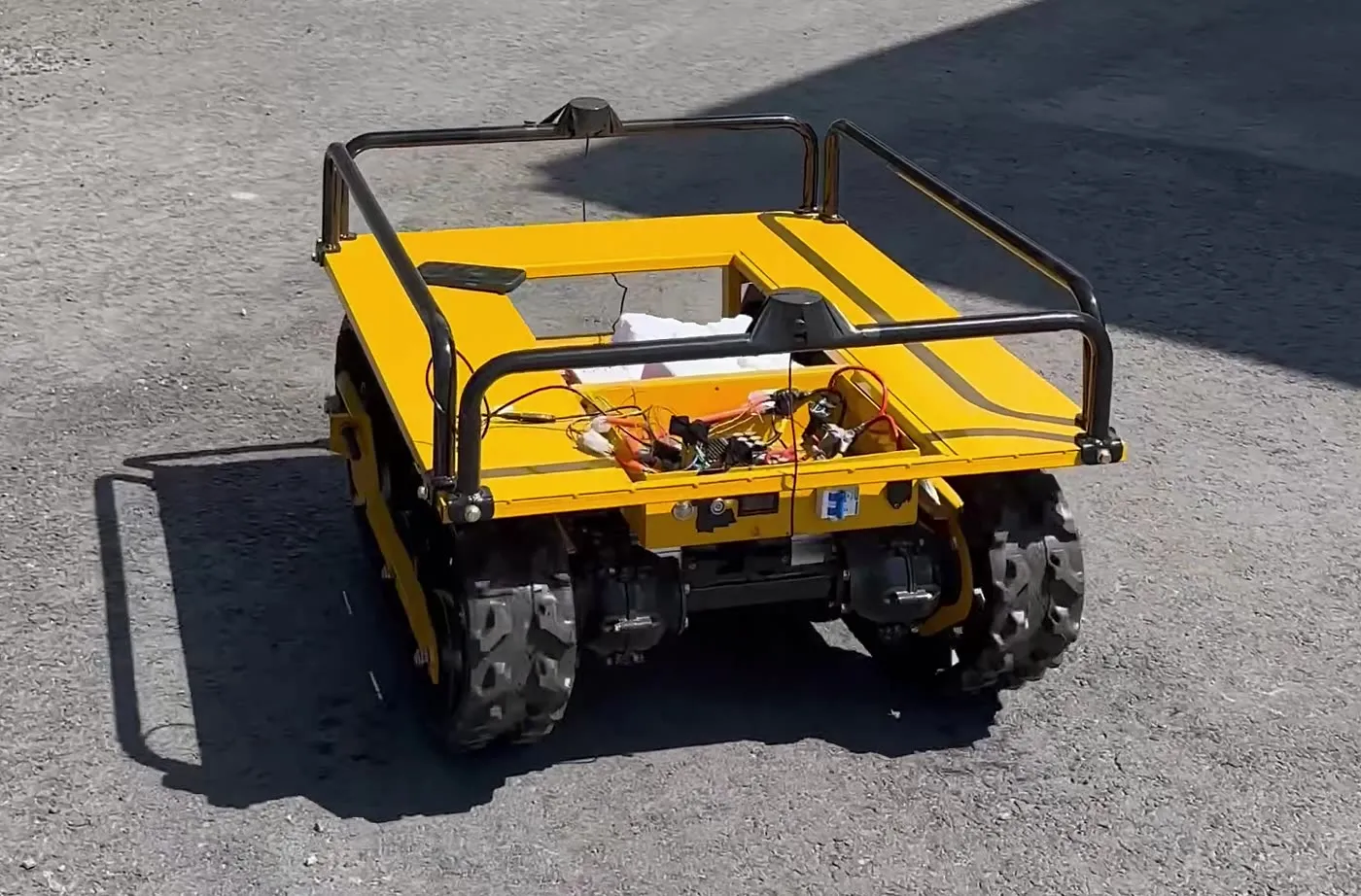
Outdoor autonomy stacks tend to be written for one robot. The kinematics, the sensor set and the tuning end up braided through the navigation code, and moving to a second platform means rewriting rather than reconfiguring.
Pathfinder is the opposite exercise. One ROS 2 autonomy architecture — dual-EKF RTK localization, Nav2 waypoint navigation and a micro-ROS motor interface — is carried across three physically different ground vehicles: a tracked skid-steer UGV, a 4×4 differential rover, and an Ackermann RC crawler with no wheel encoders at all.
Each vehicle is maintained on its own branch with its own kinematics, sensor set and field-validated tuning. What has to stay identical is everything above the motor interface. What is allowed to change is configuration.
The system
Sensing → localization → navigation → motors
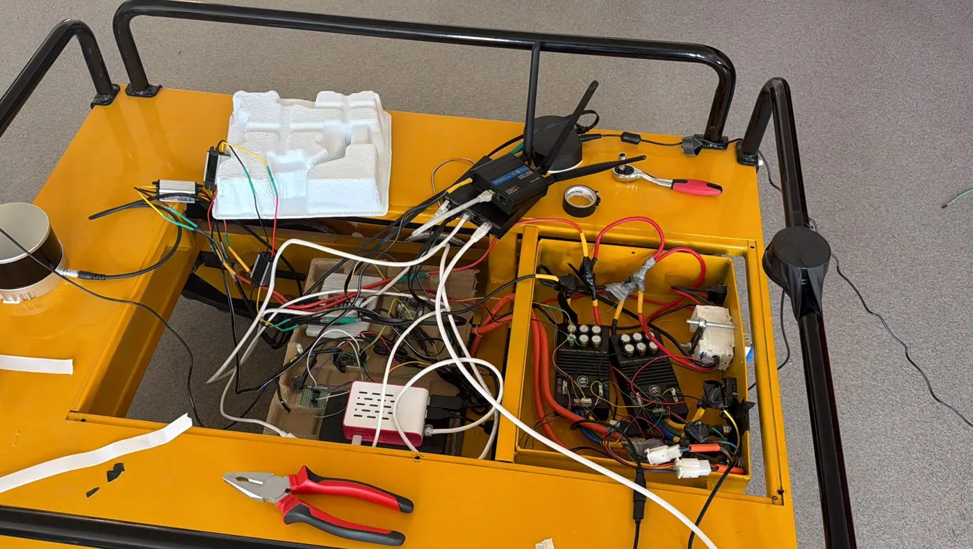
Every vehicle runs a Raspberry Pi 5 with ROS 2 Humble in Docker, an RTK GNSS receiver providing position and dual-antenna heading, a BNO055 IMU over UART, and an ESP32-S3 running micro-ROS behind the motor interface.
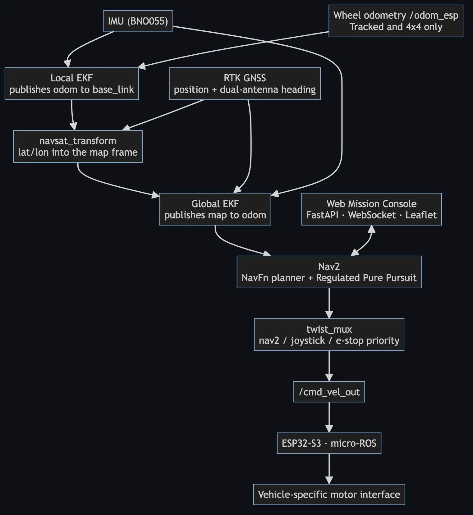
Localization is a dual EKF from robot_localization. A local
filter fuses wheel odometry and gyro to publish a smooth, continuous
odom → base_link. A global filter fuses RTK position and absolute GNSS
heading to publish map → odom, anchoring everything to real-world
coordinates. navsat_transform converts latitude and longitude into the map
frame between them.
Nav2 plans with NavFn and tracks with a Regulated Pure Pursuit controller, retuned per
vehicle. twist_mux arbitrates between navigation, the operator joystick and
the emergency stop, and publishes the result on /cmd_vel_out.
Architecture
The abstraction boundary is two topics
The boundary between shared autonomy and vehicle-specific hardware is exactly two
topics: /cmd_vel_out going down, and /odom_esp coming back.
Everything above that line — the dual EKF, navsat_transform, Nav2, the
mission console — is identical across the fleet. Everything below it is the vehicle:
tracks, four wheels, or a steering servo. Porting to a new platform means writing the
firmware behind the boundary and retuning the layer above it, not rewriting the
autonomy.
Engineering work
What I implemented
The autonomy stack, the localization configuration and the operator tooling, carried across all three platforms:
- A custom ROS 2 driver for the dual-antenna RTK GNSS receiver — binary protocol parsing, position and absolute heading, and an integrated NTRIP client injecting RTK corrections in real time.
-
Dual-EKF localization in
robot_localization: separating relative gyro yaw from absolute GNSS heading across the local and global filters, and configuringnavsat_transformso the map frame is anchored correctly. - A datum node that waits for several consistent RTK-fixed positions and a valid heading before fixing the map origin, so one bad fix during acquisition cannot offset the entire map.
- Nav2 bring-up and per-vehicle tuning — planner and controller configuration, costmap footprints, kinematic limits, and behaviour-tree selection.
-
The
/cmd_vel_outand/odom_espboundary to the ESP32-S3 micro-ROS motor interface, plus a yaw-priority velocity budget enforced in firmware. - A browser-based mission console: a FastAPI and WebSocket backend bridging ROS 2 to a Leaflet map front end for waypoint missions, live telemetry and emergency stop.
- Field tooling — wheel-odometry scale calibrated against pure RTK displacement, and JSONL mission recording so tuning changes are argued from logs rather than impressions.
The vehicles
Three platforms, three drive geometries, three different reasons the localization stack had to be argued from first principles.
Tracked UGV
Tracked skid-steer · 1.0 × 0.74 m · 0.625 m between track centrelines
| Drive | Tracked, differential / skid-steer |
|---|---|
| Compute | Raspberry Pi 5 · ROS 2 Humble in Docker |
| Motor control | ESP32-S3 micro-ROS bridge to the drive controllers |
| Positioning | RTK GNSS at 20 Hz with dual-antenna heading |
| IMU | BNO055 over UART |
| Perception | Hesai XT16 3D LiDAR — visualisation only |
| Localization | Dual EKF — wheel odometry and gyro locally, RTK and GNSS heading globally |
| Navigation | Nav2, Regulated Pure Pursuit, ~0.95 m/s target, plus a planner-free straight-line mode |
Challenge —
velocity budgeting
On a skid-steer platform each track's speed is the sum of the body's linear and angular commands:
vtrack = v ± ω · (track separation / 2)
Ask for speed and yaw at the same time and the outer track saturates, the turn degrades, and the vehicle drifts off the path. The fix is a yaw-priority budget enforced in firmware: the commanded turn rate is always delivered in full, and forward speed is clipped to whatever headroom remains. Nav2's regulated speed scaling handles it feed-forward; the firmware budget guarantees it.
Streaming the LiDAR's 2.4 MB point cloud at 10 Hz over the vehicle's own WiFi needed CycloneDDS tuning — unicast data with multicast limited to discovery, and a 10 MB socket receive buffer — to stop fragment loss.
The LiDAR feeds the mission console's 2D obstacle view. It is not wired into the Nav2 costmaps, and this vehicle does not perform autonomous obstacle avoidance.
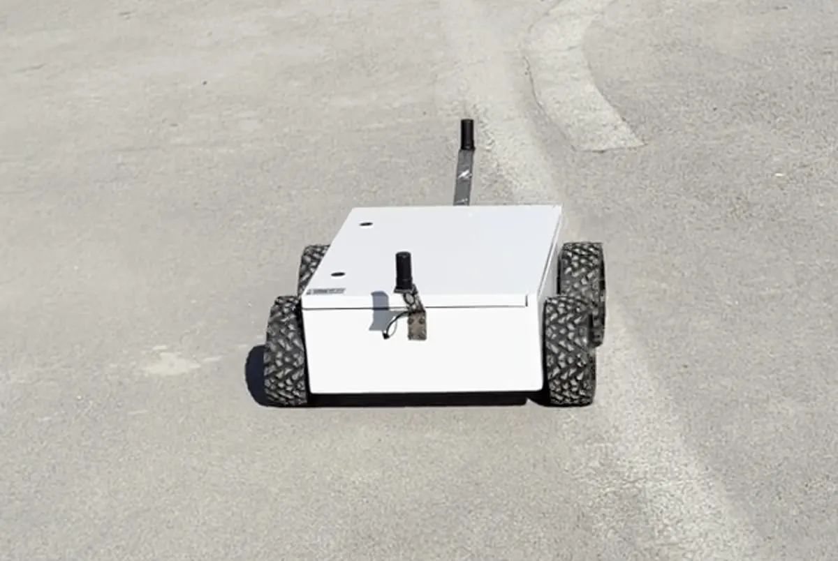
4×4 UGV
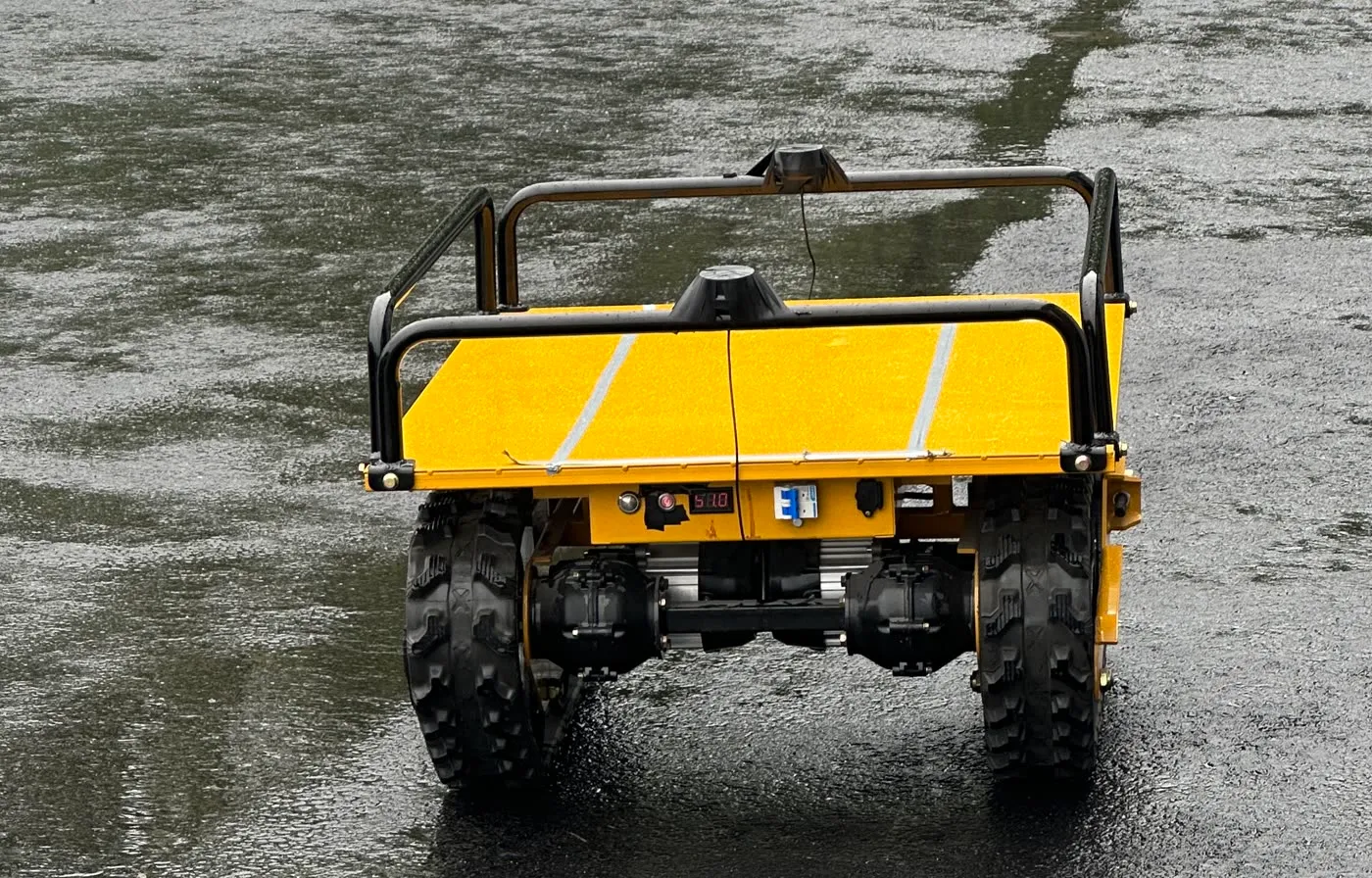
4-wheel differential · 0.5 × 0.4 m · where the localization stack was brought to a working state
| Drive | 4-wheel differential (skid) drive |
|---|---|
| Compute | Raspberry Pi 5 · ROS 2 Humble in Docker |
| Motor control | ESP32-S3 micro-ROS → 2 × RoboClaw, closed-loop velocity on the controllers |
| Positioning | RTK GNSS with dual-antenna heading, binary protocol parsed in a custom driver |
| IMU | BNO055 over UART |
| Localization | Dual EKF — wheel odometry and gyro locally, RTK and GNSS heading globally |
| Navigation | Nav2, Regulated Pure Pursuit, 0.8 m/s target, rotate-to-heading enabled |
Challenge —
heading and datum correctness
Outdoor GPS navigation fails in a specific and confusing way when heading is wrong: the vehicle drives confidently in the wrong direction. This platform is where that got solved, and the fix is a separation of two different yaw signals.
Relative gyro yaw feeds the local filter. It starts at zero wherever the vehicle happens to be pointing, and it only has to be smooth — it makes short-term motion continuous and jitter-free.
Absolute GNSS heading, from the dual-antenna receiver, feeds the global filter. It is slower, but it is true north, and it is what anchors the map frame.
Mixing them — or letting relative yaw into the global filter — produces a vehicle that navigates smoothly along the wrong bearing. Keeping them in separate filters is what makes waypoint missions land where they should.
The map origin is set the same way. A dedicated node waits for several consistent RTK-fixed positions and a valid heading before it fixes the datum, so a single bad fix during acquisition cannot offset the entire map.
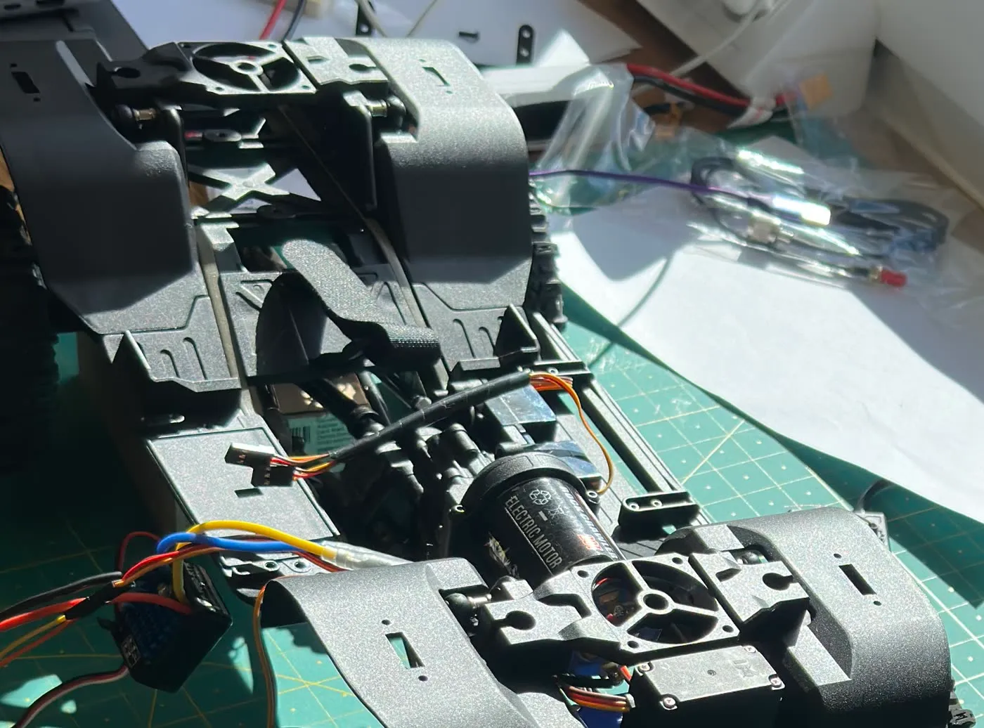
RC Crawler
Ackermann steering · 0.313 m wheelbase · up to 46° · no wheel encoders anywhere on the vehicle
| Drive | Ackermann steering, 0.313 m wheelbase, up to 46° |
|---|---|
| Compute | Raspberry Pi 5 · ROS 2 Humble in Docker |
| Motor control | ESP32-S3 micro-ROS bridge |
| Positioning | RTK GNSS at 20 Hz with dual-antenna heading |
| IMU | BNO055 over UART |
| Wheel odometry | None |
| Navigation | Nav2 tuned for non-holonomic motion — up to 1.6 m/s, reversing enabled, rotate-to-heading disabled, recovery-free behaviour trees |
Challenge —
localization with no odometry
With no encoders there is no dead-reckoning source. The accelerometer is not a substitute: integrating it twice with no absolute reference to correct against guarantees the position runs away. So the local filter is deliberately reduced to a heading estimator — gyro only, accelerometer explicitly disabled — and all position information comes from RTK GNSS through the global filter.
That topology has a trap. If the GPS-derived odometry is published in the
odom frame and then fed back into the filter that produces
map → odom, the estimate reinforces its own error and the vehicle's
position drifts away without bound. Resolving it meant referencing the GPS
conversion to the global estimate so its output lands in the map
frame, breaking the loop.
The correction is documented at the point where it matters, and a diagnostic script asserts on a live system that the fix is actually in effect — so the bug cannot quietly return after a config change.
Nav2 needed matching treatment. A car cannot spin in place or shuffle backwards out of trouble, so the default spin and back-up recoveries are removed entirely and replaced with recovery-free behaviour trees, with reversing allowed as a deliberate manoeuvre instead.
Mission console
FastAPI · WebSocket · Leaflet
A FastAPI service bridges ROS 2 to a browser over WebSocket, with a Leaflet map front end. Verified functionality:
- Click the map to append waypoints, drag to reorder, delete individually, then send the mission to Nav2.
- Position, speed, heading and GNSS fix quality — including RTK FIX state — streamed continuously.
- The driven path drawn on the map alongside the planned route.
- Send, cancel, and an emergency stop that publishes a zero velocity command at the highest mux priority.
- A manual on-screen joystick that drives the vehicle through the same arbitration chain.
Result and scope
What it does, and what it does not
Three physical vehicles, three drive geometries, one autonomy architecture. All three run outdoors on real hardware, navigating GPS waypoint missions with RTK-corrected GNSS and dual-antenna heading.
The evidence is the footage above: every clip on this page is a physical vehicle outdoors, not a simulator. Wheel-odometry scale was calibrated against pure RTK displacement rather than estimated, and missions are recorded to JSONL — waypoints, plan, pose, commands and RTK status — so tuning is argued from logs.
Scope limits
- Navigation is outdoor GPS waypoint following. There is no SLAM and no map building.
- There is no simulation — all development and tuning was done on physical hardware outdoors.
- The costmaps carry no obstacle sensor, so there is no autonomous obstacle avoidance. The tracked vehicle's LiDAR is a visualisation feed only.
- Vehicles are maintained on separate branches, not selected at runtime from a single configurable package.
Tech stack
Autonomy
- ROS 2 Humble
- Nav2
- NavFn planner
- Regulated Pure Pursuit
- twist_mux
Localization
- robot_localization
- Dual EKF
- navsat_transform
- RTK GNSS
- Dual-antenna heading
- NTRIP client
- BNO055 IMU
Embedded
- ESP32-S3
- micro-ROS
- RoboClaw controllers
- Wheel encoders
Platform
- Raspberry Pi 5
- Docker
- C++
- Python
- FastAPI
- Leaflet
- CycloneDDS